ECG Filter Investigation
Written on November 9th, 2018 by Dan Peluso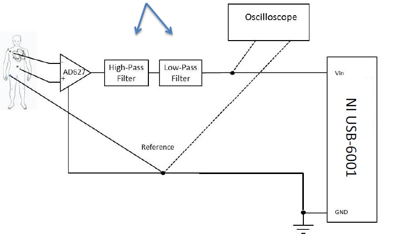
Motivations
For my circuits and signals class, the final project was to design a circuit with breadboards that reads the pulmonary signals off the chest of a participant and captures the new signal with a DAC. Above is a picture of the modular diagram.
The procedure involved the building of this circuit, including the testing of multiple configurations of filters followed by the analyzing of the results using the popular MATLAB software.
Circuit Design
 The first piece of our design was adding an AD627 noise reducing high pass filer. We tried using multiple combinations of resistors and capacitors which would result in a cutoff frequency of about .05 Hz, and eventually ended up using two 6.8μF capacitors at the input, and two 510 kΩ resistors which connected in parallel to the input capacitors and led to ground. The value for 𝑅𝐺 was then considered. This value was found to be 25, which contributed to the overall amplification of the ECG signal. For this, we decided it would be best to use an LM358 op amp.
The next piece of the circuit needed to filter out the high frequencies. To modify the gain of this circuit and further amplify the ECG signal, we used a source resistor value of 10 kΩ and a parallel resistor value of 200 kΩ. This gives the circuit a gain of 20.The parallel capacitor had a capacitance of 6.2 nF. The following figure diagrams the configuration of these components:

In a similar powering method to the AD627, 1.5V batteries were used to power this component. From these component values, the overall cutoff frequency (see Appendix 2) was calculated to be 128.35 Hz. While this was a bit below the expected frequency we normally would like to see coming from an ECG signal, we thought it reduced the noise to a reasonable level. It is essential to have the circuit low pass filter after the high pass because of the restrictive nature of a high pass filter. It is first necessary to remove the DC components of a signal before putting it through a low pass to remove the noise. Both filters must also be after the noise reducer op amp we first used. This is so that the noise is least modified by the gain of any amp and the filters have much less frequencies to remove. We did not use additional capacitors for the power supply of the low pass filter, because we did not think it was necessary for additional noise removal. It is also essential to remove high pass noise before the A/D DAQ is configured. This is so that any discrete analysis of the signal is not grossly inaccurate from noise.
Digital Analysis
The following voltage plot was produced from the discrete sampling of the ECG signal after going through our circuit.

Here is the Parks-McClellan Filter Output:

The final piece was to try to figure out the BPM of the heartbeat recorded with a full frequency spectrum plot. This can be easily done by looking at the first frequency peak in the plot. Here is a zoomed in capture of the plot from MATLAB:

Skills
- MATLAB
- Noise filters
- Parks-McClellan filters
- DAC Signal Analysis
- FFT
- Human Signals Input